This website is really part blog, part archive of what I call Stories. Now by Stories I do not mean fiction. I mean episodes from my past ( found in the Nostalgia Wing of the House ), or thoughts about what it is all about ( found in the Philosophy Wing ), or perhaps comments about social questions ( found in the Social Activities Wing ).
Right now the House is more the size of a log cabin than a grand house with Wings and Floors and Foyers. But I hope it will grow in time.
Click on ‘Blog Feed’ to get to the Blog part of the website, which is where you are now. Here I introduce the stories and ask for your comments. To make comments on a Story come out here to the blog. If the Story is not a recent one then you can make your comments under this post.
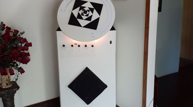
I completed my Big Radio project on 18 June 2020 This has been occupying my time since March of 2018.
Objective
I have always liked the look of big old console radios. Table top radios, such a cathedral style, or tombstone style are nice, but it is the big floor standing models that really get my attention. Especially the big round dials. And lots of tubes. The Zenith Stratosphere, the Crosley Colossus, how can you not love those.
A picture from that site gives an idea of the look I was after. I wanted sort of shoulders on the side and a slanted area in the center for the dial. Something like this : https://radioatticarchives.com/radio.htm?radio=5667
But I wanted a big round dial, not a slide rule dial, and more of an angle.
My cabinet making skills are primitive, but I thought if I built a rectangular box from 24 x 48 inch panels, then added more and more panels to the side, stacked up in clever ways, I could produce a shouldered effect.
That just did not work out.
Evolution of Cabinet My original goal was beyond me, so I simplified to just a rectangular cabinet made from pre-cut 24 x 48 inch panels.
but then I needed a way to attach a big 24 inch diameter dial at an angle to the top of that rectangular box. I thought of strange brackets and things like that but then somehow I thought of the pyramid. And to make it interesting make the triangular sides of the pyramid equilateral.
When I placed the white Big Dial onto the black Pyramid I thought there way too much white. There needed to be something added to the centre of the dial. So I added the series of alternating black and white squares. Each square is rotated 90 degrees to the one below it. They form a sort of spiralling stepped pyramid.
The side of each square is 1 over the square root of 2 times the side of the one below it. There is nothing special about that, except it works out very conveniently when the largest size is 12. This makes the black squares easy to cut : 12, 6, 3, 1.5 inches. But the white are also easy in this case since 12 over square root of 2 is very nearly 8.5 ( within .02 of an inch ). So just cut 8 1/2, 4 1/4, 2 1/8. Easy.
Dial
I wanted a dial big enough to allow each station to be indicated on the dial by its own dot. As we all know the stations on the high end of the dial get crowded closer together, assuming a normal cut tuning capacitor. For example on the radio behind me as I write this, a wooden Philips table top radio, the dial shows a dot every 10kHz, ie every station, between 540 and 700, but only labels 550, 600, 700. From 700 to 1000 it has a dot every 20 kHz, ie every second station, but only labels 700,800 and 1000. From 1000 to 1600 it has a dot every 50 kHz, ie every fifth station, but only labels at 1000, 1200, 1400, 1600. I think this is fairly typical. Back in the day you did not expect a radio dial to have the sort of resolution we have gotten used to from digitally tuned radions. But I wanted a dot for each and every station, and I wanted each and every dot to be labelled with the frequency.
So I thought, why not make the dial as wide as the whole radio, or even wider ? So a 2 foot wide dial. And use the entire circumference. The tuning capacitor only rotates 180 degrees, so I would use a pulley on the dial half size of the pulley on the tuning capacitor. This would result in 360 degrees of dial movement for 180 degrees of tuning capacitor movement.
As it turned out the pulley I had in mind for the dial did not work. I was nylon, and narrow, with a groove in it wide enough for one turn of dial cord. This did not provide nearly enough friction for the dial to turn the tuning capacitor. I had to find something that was wide enought to hold at least 5 or 6 turns of dial cord and diameter less that the tuning capacitor pulley diameter, preferably about half of that. And I didnt want to spend a lot of money buying some fancy custom sized pulley.
What I ended up using was an spool I had lying around that used to hold heat shrink sleeving. It was wide, and was made from a sort of cardboard material so it would have lots more friction than the nylon pulley. Of course there was no way to attach this sort of spool to the shaft of the dial. So I glued the nylon pulley, which had the proper diameter hole and set screw to attach to a shaft, to the spool.
The spool diameter was a bit larger than I wanted, so the dial markings do not take up the whole circumference. But they take up about two thirds, and I get the room I need to put in all my markings.
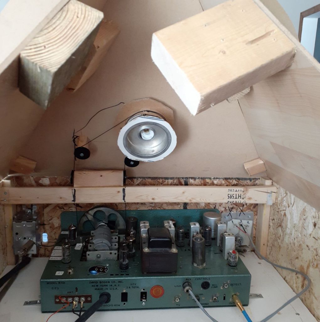
Bogen R701 AM/FM Tuner
The Bogen tuner had been aligned years ago and was in good working order. But I made a few modifications.
I removed the power wire from the main selector switch. As with the amplifier, the tuner will be powere on when the power switch on the radio is switched on.
I removed the tuning knob and the flywheel attached to it. I dont need it, on the Big Radio the Big Dial will also serve as the tuning knob. The flywheel was cracked and bent and out of balance anyway.
The Bogen documentation describes something called a Loudness Control Switch or LCS that can be plugged into a socket on the back of the chassis. I have use the tuner for years without installing this so called LCS but I thought that for this project I would go all out and add one. So I built the LCS described on the schematic, just a small board with a rotary switch and a few resistors and capacitors. It is really just a glorified tone control. I am not at all impressed with it. When switched out the tuner sounds fine. Switching to any of the other 4 settings just produces varying degrees of muffledness. I have not bothered to analyze the circuit, perhaps when I have nothing else to do.
Before removing the original dial I tweaked the alignment one last time and got the response to my satisfaction.
Then I removed the dial.
Dial Marking It took me quite a while, ie months, yes, months, to figure out how to run the dial cord. Not that it ought to take months of intense thought to figure out, just that every time I thought about it I got upset and gave up and put the whole Big Radio Project on the back burner.
The traditional method is to tie one end of the dial cord to a little bump on the tuning capacitor pulley, run the cord part way around the pulley, then wrap it around any little pulleys used to route the cord in the directions it needs to go, then 3 or 4 turns around the shaft of the tuning knob, then back to the tuning capacitor pulley where you connect one end of a spring to the end of the dial cord and the other end of the spring to another little bump on the tuning capacitor pulley. The problem with my Big Radio is that with the tuner in place, and with the Pyramid installed on top, and the Big Dial installed on the Pyramid,I could reach the dial pulley from the back of the radio, but not the tuning capacitor pulley. The back of the pyramid is open. There is no way to reach in from the back and run the cord around the tuning capacitor pulley. I cant reach from the front, the pyramid and the dial are in the way.
Eventually I came up with a solution. The key was to change the location of the spring. The Pyramid and Big Dial are removed. I cut the dial cord into two pieces. Standing in front of the radio I tied one end of one piece of dial cord to one of the little bumps on the tuning capacitor pulley and wrapped it as far as I could around the pulley. I held it in place with scotch tape. By rotating the tuning capacitor I was able to get the cord down under the pulley inside the bottom of the tuner. Then I tied one end of the other piece of dial cord to the other bump on the tuning capacitor pulley and wrapped it around in the other direction to the first piece and secured it with tape in a similar way.
I then draped the two length of dial cord over the first set of direction setting pulleys and secured with tape. This leaves the ends of two pieces of dial cord dangling inside the Big Radio, where I will be able to easily reach them when standing behind the radio.
Then the Pyramid and Big Dial were installed. Standing behind the radio I routed each dial cord around the next direction setting pulley and then 3 times around the spool/pulley connected to the shaft of the Big Dial. Then I cut back excess from the dial cords, tied the spring to the end of one dial cord, cut the other dial cord back so it is about 3 inches short of the first one, the tie it to the other end of the spring. Done. Well, almost. I had to repeat it a couple of times until I got all the slack pulled out of the dial cords. You cant just rely on the spring.
Once I had this done I could stop worrying about it and proceed with the rest of the build.
Hand Marking Dial I taped pieces of paper to the Big Dial. With a combination of using an RF signal generator and just tuning in local stations I marked the location of each AM and FM station frequency and labeled them. I had drilled 2 small holes in the dial indicator so I could mark a pencil dot at each station location.
Then I removed those papers and scanned them into jpeg files. I imported the jpeg files into my CAD program. I use TurboCAD. The jpeg images were then joined up and formed a layer in my CAD drawing. On other layers I added the circles, dots, and text that made up the “good” dial drawing and aligned with the hand written marks on the first layer.
I dont have a printer capable of printing to a 24 inch square piece of paper. I did not want to stitch together a lot of 8 1/2 x 11 pieces of paper, it never works.
So I exported the good layers to a jpeg file, and sent it to Staples to be printed onto a 24 x 26 inch sheet. Staples will do 24 x 36 inch plain printer paper for about $5 per sheet. Or they will do a 24 x 36 inch poster for $40.
I got 2 of the $5 plain paper versions. That may have been a mistake.
Mod Podge
I did an experiment with some pieces of paper to see if I could glue the paper dial to wood using ordinary wood glue. The result was very wrinkly. So I did an online search to get reccommendations about gluing paper to wood.
I saw posts with good things to say about Mod Podge. In particular a video showing some craft paper being glued to a wood panel with Mod Podge, then sealed with the same Mod Podge. I was impressed by the sealing and by the fact that they showed the paper being moved around into final position before the glue sets.
So I bought some Mod Podge online. It was ready for curbside pickup that afternoon, and I proceeded to glue on my Big Dial drawing.
It was a disaster.
The paper wrinkled up. It would not move into position with out tearing. The glue set very quickly. Maybe the heat, maybe humidity ? I was doing this in my garage. I could not get the complete circle to go down flat.
I had to rip off all the paper, scrape off the glue, and start over. I am glad I bought two copies of the drawing.
Obviously the craft paper in the video is much thick than the plain printer paper of my drawing.
So I glued on the second copy. But this time cut it so it was not a complete circle. I placed it on the wood and glued it in sections. That way I was able to keep it flat. It is not in the precisely correct location, but at least it is flat and wrinkle free.
In hindsight I believe I should have spent the $40 and got the poster grade version of the drawing.
Panel Markings I did the panel marking in CAD and printed them onto transparent full sheet label material. I have used these before on other projects and they turned out OK. If you are careful you can apply these without leaving bubbles. But they have a shiny appearance that contrasts with the rest of the cabinet and I am not completely happy with how they look on this particular radio. Next time I think I would make some sort of placard and mark it, then install it to the radio. That way the contrast would clearly be deliberate.
Amplifier I decided to use an amplifier of approximately the same vintage as the Bogen tuner. Except of course it would really be built in 2018.
So I picked the ultralinear circuit published by Hafler and Keroes in the 1950’s. I had never built an ultralinear type amplifier, so I thought I would try one.
I built it more or less as published with the following execptions :
modern power wiring ie 3 prong plug, EMI filter
Hammond transformers and choke.
shielded twisted pair wiring to heaters. That is “thing” of mine.
feed back changed to produce gain suitable for input from Bogen.
The picture shows that I have covered the 6SL7 input triode tube with foil tape. I found that just putting my hand close to that tube was enough to produce a small hum. I realize that with the amp installed in the bottom of the radio nobody will be putting their hand near that tube, but still, I wanted to get rid of all hum, so I shielded the tube, and no more hum.
I have not worked on my SPICE modelling program for a few weeks now. I have been spending time on my Big Radio Project.
Now that is completed I can return to my SPICE modelling program. When last I posted I mentioned that I have run across the models of Adrian Immler and that I wanted to evaluate them and get them into my program. They look like very good models, assuming you can extact parameters for them that will fit your data.
I have not been able to do that very well programmatically. His models do not reduce into simple explicit equations of independant variables. Which is fine for SPICE, a SPICE engine is meant to handle that.
But it is not fine for the non linear regression I want to do to extract model parameters. I have tried every trick and simplification I know, and I can get things to work not too badly for small amounts of data, but I am really not satisfied with it. I have put in the ability to plot the results of the model against the measured data so the user can interactively change the parameter values and see the results. This may be the only way to get a good fit to the data for the Immler models. But it doesnt allow the automated parameter extraction and model comparison that the program is intended to do.
The other thing to do of course is use the models provided by Adrian Immler.
So why not just release the program as it is now, with the understanding that the Immler models are not automated ? Because there are other things I need to clean up. As it is now it is just something I use, I need to clean up the menus, and remove things that dont work, or features I started to add but didnt finish etc.
I have set a target of Sept 1 to finish this program. Oh, I forgot to say what yeare. OK, Sept 1 2020.
I have not posted to my blog, or even looked at it, for quite some time. ( February 24 in fact)
It may be that I prefer doing things to writing about doing things, or it may be just laziness.
My main focus prior to abandoning my blog was on SPICE modelling. In my next post I will go into more detail about the problems I am having on that front.
And in the the post after that I will talk about my Big Radio project, which illustrates what I meant about doing things rather thatn writing about things.
I know everybody has to find a way to prioritize and get things done. I am certainly not the only one who cant seem to find enough hours in a day. For some time I have my house cleaning with a check list I stick on my refrigerator. By following this schedule I keep my house from turning into some sort of slum dwelling. It really works for me.
I think I will make a similar schedule or check list of things to do each day or each week : blog writing work, radio project work, SPICE modelling program work, chess practice work, exercise work, golf practice work, project Euler work, armchair philosophising work, etc.
Now I just need to schedule some time to make a schedule.
I has been some time since I have posted anything in my series of SPICE modelling stories. There are two reasons. I have taken some time to look over the triode and the pentode models of Adrian Immler. I have been successful in updating my program to do parameter extractions for Immler’s triode model. His pentode model is giving me a little bit more trouble. I need to do a bit more work. The second reason is that I have switched from using FreePascal and the Lazarus IDE, and am now using Embarcadero Delphi. They are both Pascal at heart, so the change was not difficult, but it did take some time. I hope to be able to make a post about Immler’s models soon.